

 CN
CN



 Fill out a inquiry form




Driving LEDs and Piezo Buzzers together, Lumissil's Approach to Simplify IoT Designs
Driving LEDs and Piezo Buzzers together, Lumissil's Approach to Simplify IoT Designs
Driving LEDs and Piezo Buzzers Together, Lumissil’s Approach to Simplify IoT Designs
Ever wondered if your LED driver could do more than just light up LEDs? What if it could also make your system beep without adding extra dedicated ICs? Yes, you read that right, Lumissil FxLED Drivers has the technical tendency to support this type of application requirements, with just a few additional components you can drive both RGB LEDs and a simple passive piezo electronic buzzer. With fewer additional components comes reduced BOM cost and flexibility in the layout design, without the need for additional piezo driver also saves PCB layout space. With the benefits of driving two or more components with one IC, having dual functionality becomes a bonus factor in modern consumer electronics designs. This totally reduces the form factor which enables in producing much sleeker and compact consumer electronic products.
HOW LED DRIVERS WORK?
LED Drivers are constant current regulating devices. Because LEDs are current-driven, they require a well-managed current supply to guarantee uniform light output and prevent failure. Multichannel drivers like Lumissil’s IS31FL320x family (see table 1) take this step further by giving each channel its own programmable pulse width modulated (PWM) signal. PWM rapidly turns the LED on and off at a fixed frequency while adjusting the duty cycle, which controls the brightness in fine steps. This constant switching actively shapes the output waveform for each channel. Because these PWM outputs are clean, stable square waves, similar to the waveform a piezo transducer requires, an LED driver channel can be repurposed as a simple audio output. In other words, LED drivers generate a similar type of PWM signal that can also drive a simple passive piezo transducer.
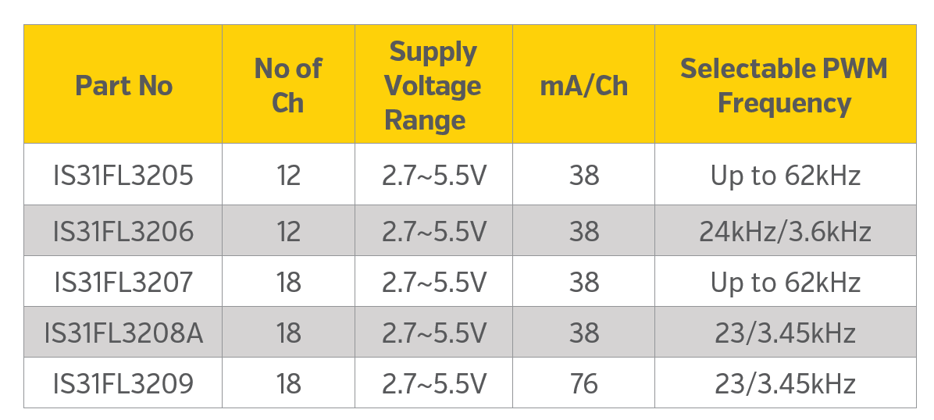
Table 1: Example of Lumissil Multi-Channel LED Drivers
HOW DO PIEZO BUZZERS WORK?
A piezo buzzer is an acoustic transducer that converts electrical energy into sound using the piezoelectric effect. There are two types of piezo buzzers, Active (with Oscillator inbuilt) and Passive which needs external PWM pulses to control the pitch and tone. At the core, there is a thin ceramic disc bonded to a metal plate. When an electric signal is applied, the ceramic material physically flexes expanding and contracting in response to the voltage. If the signal is a steady DC signal, nothing audible happens, but instead if the signal is an AC waveform, such as a PWM square wave, the ceramic is excited and vibrates rapidly. Thus, when the PWM frequency matches the buzzers’ resonant frequency (typically between 2-5 kHz) it produces a loud, clear tone. Piezo buzzers are high-impedance, capacitive loads and draw very little current, and can operate anywhere between 3 – 250Volts. This makes it ideal to be driven by a low power PWM waveform generated by an LED driver channel output.
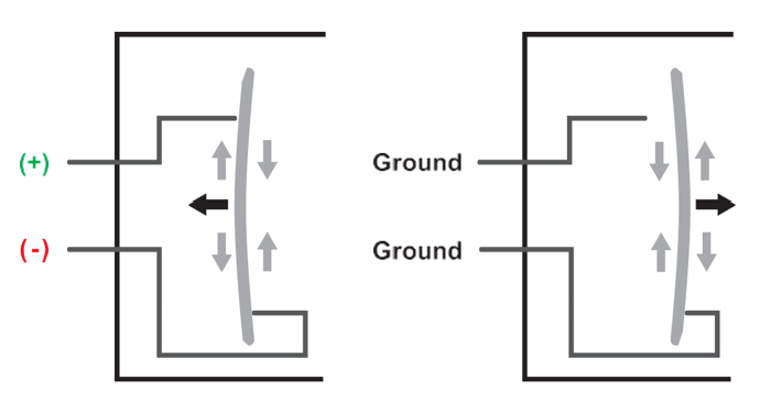
Figure 1: Piezo Transducer Activation
WHY USE AN LED DRIVER TO DRIVE A PIEZO BUZZER?
Consumer electronic products from appliances to IOT gadgets often need both visual (LED) and audible (tones) as feedback for user input. Traditionally, the buzzer requires a dedicated driver. However, Lumissil LED drivers can already generate PWM outputs, provide accurate current control, interface via I2C/ SPI. In addition, some LED drivers offer PWM frequencies in the kHz audio range, enabling tone generation while maintaining acceptable LED performance without noticeable visual degradation. Lumissil LED drivers such as the IS31FL3206, IS31FL3207, and the IS31FL320x family can handle both tasks due to their configurable PWM frequency. For example, the IS31FL3206 can go as low as 3.6kHz with 8-bit duty-cycle resolution, allowing designers to select a piezo transducer with a resonant frequency in that range. Another example is the IS31FL3207 which can go as low as 122Hz while maintaining 16-bit duty cycle resolution. The resolution of the duty cycle matters as it helps to adjust the PWM pulses, which is directionally proportional to the loudness of the buzzer.
PRACTICAL HARDWARE IMPLEMENTATION
The duty cycle controls the piezo transducer’s loudness, therefore adjusting the PWM duty can produce varying levels of loudness. Let’s take a piezo buzzer from Soberton Inc PB-3020-2 for this example. It operates from 3- 20V DC and has a rated frequency of 3900±500Hz. As shown in Figure 2, the buzzer is connected to the LED driver with its anode tied to VCC (5V), and a 2KΩ resistor is connected in parallel with the buzzer. This resistor creates a discharge path for the piezo buzzer’s high impedance capacitive load and helps prevent the channel from remaining in ‘float’ state when it is in a high impedance (off) state. Similarly, there is a resistor R2 450Ω connected in series between OUT1 and piezo cathode, limits the instantaneous charge/discharge current on PWM edges and adds damping to help reduce ringing and EMI. With the hardware portion of this circuit complete, the next step is to program the software registers in IS31FL3206 to drive the passive piezo buzzer.
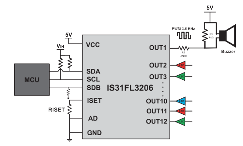 Figure 2: Buzzer connected to channel 1 of IS31FL3206
SOFTWARE IMPLEMENTATION
Any output channel from the IS31FL3206 can be repurposed to drive a piezo buzzer. Since each of the 12 constant current sink outputs is capable of generating a PWM signal. For this example, we are using OUT1 as the dedicated piezo buzzer drive output. Before configuring the IS31FL3206 in software, set the global maximum current using the RISET resistor. For this example, let’s connect a 10KΩ resistor between ISET and GND to set the global maximum current between 2~3 mA.
The implementation requires configuring the following on the device:
- Programming the Global PWM switching frequency to 3.6KHz, i.e. resonant range of most piezo
buzzers - Enabling the OUT1 Channel
- Setting its PWM duty cycle (Buzzer volume)
1) Setting the Audible PWM register as 3.6KHz (27h)
Set Output Frequency register 0x27 = 0x01 → 3.6 kHz for all channels (audible) by default the IS31FL3206 frequency is set at 24KHz
2) Enabling OUT1 via the LED control Register (17h)
Each channel has a dedicated control register from 17h~22h, with OUT1 mapped to register 17h. This controls both channel-enable and current scaling (SL)
Write 0x10 to LED Control register for OUT1 (0x17) to enable at IMAX
3) Setting OUT1 Duty Cycle Register (04h)
Write a value 0–255 to PWM register for OUT1 (0x04)
With the registers configured as shown above, the buzzer produces a constant tone at the programmed duty cycle. To adjust loudness on the fly, write a new 0-255 PWM value to OUT1(0x04) and update the PWM register(0x13) each time you want the change to take effect.
PRACTICAL CAVEATS
Changing pitch with PWM duty is not possible due to the fixed PWM frequency in the above example, the frequency is set to 3.6kHz.
Driving piezo and LEDs at two different frequencies is not possible; the limitation is that each LED driver has a single PWM engine which synchronizes the PWM frequency for all output channels.
Driving an active buzzer with a constant-current sink output is not possible, since active buzzers expect a DC power source.
Output headroom (VHR) applies when an OUTx channel is used as a constant current LED sink. In that mode, the OUTx pin must maintain sufficient voltage across the internal current regulator (typically 0.4~0.6V) in order to stay in regulation. (This headroom voltage requirement applies to LED current regulation; it is not a requirement for piezo drive operation, which is used as a PWM load switcher.)
If all you need is a simple, fixed pitch audible alert for your IOT design, you can repurpose an OUTx channel on a Lumissil FxLED driver such as IS31FL320X to excite a passive piezo transducer. This approach leverages the LED driver’s existing PWM capability to provide audible feedback with no additional buzzer IC or layout penalty and saves BOM cost. This shows the flexibility of Lumissil LED drivers beyond LED indication, but also for IOT applications that require driving a simple passive piezo buzzer.
About Lumissil Microsystems
Lumissil Microsystems specializing in analog/mixed-signal products for automotive, communications, industrial, and consumer markets. Lumissil's primary products are LED drivers for low to mid-power RGB color mixing and high-power lighting applications. Other products include audio, sensors, high-speed wire communications, optical networking, and application specific microcontrollers. Lumissil Microsystems has worldwide ofices in the US Taiwan, Japan, Singapore, mainland China, Europe, Hong Kong, India, and Korea.



 analog@lumissil.com